
 By
By 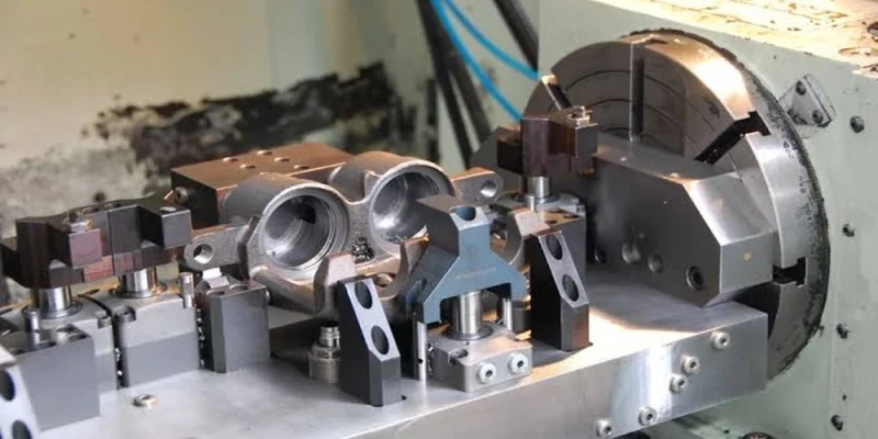
Welding positioners are often purchased with one number in mind: rated load. That number matters, but it does not decide whether a real fabricated part can be held, tilted, rotated, welded, inspected, and removed with confidence. Lopsided weldments, extended fixtures, changing centers of gravity, and difficult access routes can turn nominally adequate machines into daily sources of setup delay.
Positioner selection should be based on a documented rotation case, not a bare mass figure. Document the workpiece, fixture, center of gravity, orientation, motion, process, control method, and recovery conditions. Once the case exists, a buyer and supplier can judge whether a standard platform is appropriate or whether the job needs a different configuration.
Why rated capacity alone creates false confidence
A rated load is usually presented under defined conditions. Real fabrications may place that mass away from the rotation axis, carry a long fixture, include a one-sided nozzle, or require tilt before welding. Each condition changes the force and control problem. Compact, centered loads can be easy; extended or offset ones can be difficult.
That is why a buyer should never communicate only a total weight. Provide the workpiece drawing, fixture concept, center-of-gravity estimate, maximum distance from the relevant axis, required orientations, and the intended load/unload method. If the center of gravity is uncertain, say so rather than quietly assuming a nominal position. Suppliers can then identify what must be calculated, tested, or redesigned.
Ergonomic exposure is part of the calculation too. Properly selected positioners can reduce the need for a welder to reach, climb, or repeatedly reorient a component, but poor fixtures can create new handling risks. OSHA’s ergonomics guidance highlights the importance of addressing force and awkward posture in work design; a rotation system should make the job more controlled, not simply move the awkwardness elsewhere.
Three-Point Rotation Verification
This compact protocol asks the team to verify three separate conditions before choosing a model.
First, test hold: can the fixture and clamping method retain the actual workpiece through all planned orientations without slip, distortion, or an undefined manual intervention?
Next, verify movement: can the equipment provide the needed rotation and tilt range, speed control, start/stop behavior, and repeatability for the weld and inspection sequence?
Finally, check recovery: can an operator safely load, stop, inspect, adjust, unload, and respond to an abnormal condition without bypassing the intended controls?
Each point must be tested with the least favorable credible condition, not just the neatest demonstration part. Useful outcomes include a written engineering question list covering clamp load, fixture stiffness, eccentric load, tilt sequence, cable management, control location, emergency stop behavior, and required acceptance evidence. This protocol does not replace detailed engineering; it makes sure detailed engineering starts from the right facts.
Before asking Aubrik for a positioner quotation, attach the same hold-move-recover record to the request, including the fixture drawing and least-favorable orientation. Attached evidence gives the applications review a clear basis for identifying whether the proposed arrangement needs a different workholding route.
Turn mass, offset, and fixture into a real load case
Start by drawing the full rotating assembly: workpiece, chuck or faceplate, adapter, jaws, temporary tooling, and any tailstock or support arrangement. Identify the mass of each element, its approximate center, and the maximum offset from the rotation axis. Then list every orientation the unit must reach. Parts that are stable horizontally may have very different loading conditions during tilt.
Input to documentWhy it mattersHow to validate it
Total rotating massSets the baseline structural and drive demandWeigh components or use controlled bill-of-material data
Center-of-gravity positionChanges torque and stability during rotation or tiltCAD estimate, rigging review, or controlled trial
Fixture overhangCan increase deflection and change accessFixture drawing with reference dimensions
Required orientationsDefines the least favorable motion conditionWeld-sequence and inspection plan
Load/unload routeDetermines clearance, lifting, and operator exposureLayout and rigging sketch
Do not assume a fixture is neutral. Fixtures may be the largest contributors to offset or the components that determine whether a seam is accessible. Suppliers need this information to assess the full assembly rather than a fictitious centered load. That information is also the basis for deciding whether a headstock-tailstock configuration, a purpose-built cradle, or an alternative workholding route is more suitable.
Match motion modes to weld geometry
Rotation can mean continuous slow travel for a circumferential weld, indexed movement between short seams, a controlled tilt to bring a joint into a favorable position, or a combination of motions during fit-up and inspection. Describe the desired result in process terms. State the weld process, joint type, required torch access, target orientation, tolerance for starts and stops, and whether the operator controls motion directly or works from a defined sequence.
On the current Aubrik positioner page, the company publishes a broad family range and lists representative parameters such as 50 kg to 50 t capacity, 0.03-30 RPM stepless speed, and 0-135 degrees of tilt for its described positioner offering. Those figures are useful for framing an initial discussion, but they must never be read as a blanket approval for every attachment, offset, or duty cycle. Final suitability depends on the validated load case and the supplier’s applicable configuration.
For TIG work or a process that benefits from a very controlled travel rate, the useful question is whether the control system delivers stable motion through the actual speed window and load condition. For a heavy fabrication that needs only index positions, a different control strategy may be more relevant than maximum speed. Separating the process need from the brochure number makes the specification more honest.
Choose a positioner family from part behavior.
Compact parts with repeatable geometry may suit a turntable-style route. Fabrications that require a chuck and tilt may call for a rotary positioner. Long pipes or vessels can require a pipe-positioner or roller-based arrangement, while very large or demanding parts may need a heavy-duty headstock-tailstock system and custom workholding. Part behavior while supported should determine the choice, not the strongest-sounding product label.
Aubrik’s positioner page describes turntable, rotary, pipe, and heavy-duty families, with different workpiece ranges and control routes. That taxonomy is valuable because it forces a buyer to discuss the workpiece class before narrowing the model. When assessing workpiece rotation equipment for complex welds, ask the supplier to state which family is being proposed, what assumptions make it appropriate, and what different family it would recommend if the load case changes.
Put controls and safety constraints into acceptance criteria
Controls are not a minor accessory. Specify whether the operator needs a foot control, pendant, remote station, preset positions, speed adjustment, or integration with a welding cell. State where controls must be reachable during loading, welding, inspection, and abnormal recovery. Define expected behavior for a stop command, power interruption, restart, and a changed fixture. Include cable and hose routing so that rotation does not create a hidden entanglement route.
ISO 12100 provides a machinery risk-assessment and risk-reduction framework. In practical terms, this means the actual combination of positioner, fixture, clamp, workpiece, controls, and surrounding cell needs to be evaluated as a system. Guarding, safe distance, emergency stops, authorized operating modes, and foreseeable misuse should be part of the installation plan rather than optional extras.
Run an acceptance test that resembles production
A positioner acceptance test should not be limited to an unloaded rotation video. Create a short protocol using an actual part or an approved representative assembly. Include loading, clamping, initial movement, the most demanding tilt or rotation condition, speed adjustment, a planned stop, restart, operator access, inspection position, and unloading. Record the fixture used, assumed center of gravity, controls tested, and any exceptions.
If the final workpiece is not available, document exactly what the surrogate does not reproduce: mass, offset, surface condition, overhang, clamp interface, or weld-head clearance. This protects both buyer and supplier from treating a convenient demonstration as proof of the final application. The evidence also makes later commissioning faster because the acceptance criteria already describe the production reality.
What a positioner will not solve.
A positioner cannot correct poor part fit-up, inconsistent incoming geometry, insufficient lifting capacity, bad fixture design, or an unsuitable welding process. Bringing the joint into an accessible orientation may make those problems more visible, but it does not remove their cause. High-mix shops may also find that frequent fixture changes and setup verification consume more time than expected.
There is a real trade-off between flexibility and dedicated repeatability. Versatile platforms can accommodate different work, but they need disciplined setup and may not give the fastest changeovers. Dedicated fixtures can stabilize high-volume families, but they can become stranded assets if the product changes. Annual volume, part variability, quality exposure, and the cost of controlling a mistake should determine the balance — not the largest published capacity.
Build the request for quotation from evidence.
Useful requests for quotation include the load-case drawing, photos or CAD of the part and fixture, center-of-gravity assumptions, required orientations, weld sequence, desired motion modes, available utilities, layout, loading plan, safety expectations, control requirements, records, training, and a Three-Point Rotation Verification result. Require the supplier to identify exclusions, fixture responsibility, control scope, and acceptance tests.
Evidence-driven requests give buyers a much stronger basis for comparing alternatives. Positioners earn their value when they make the weld route safer, more repeatable, and easier to verify with the actual workpiece. Rated load then becomes one important input in a complete engineering decision, rather than the only number on the page.







Comments